IntraSense+: Electrophysiology Inside Intact Organoids
How IntraSense+ places silicon probe sites inside a brain organoid, what the recordings look like, and how it is configured and ordered. PDF note attached.
10 min read
Updated October 26, 2026

NeuroNexus · neuronexus.com · Resources
IntraSense+ records electrical activity from inside intact brain organoids. Silicon probe shanks with sites at chosen depths enter the organoid, which rests in a sample chamber inside a standard incubator with a camera on the probe–tissue interface; a NeuroNexus data acquisition system and Radiens ↗ record and analyze the signals. In one NeuroNexus dataset, 834 of 1,056 sites recorded activity. The system is configured per organoid and available by quote.
Research use only. NeuroNexus products are for non-clinical research use and must not be used in human or veterinary medical procedures.
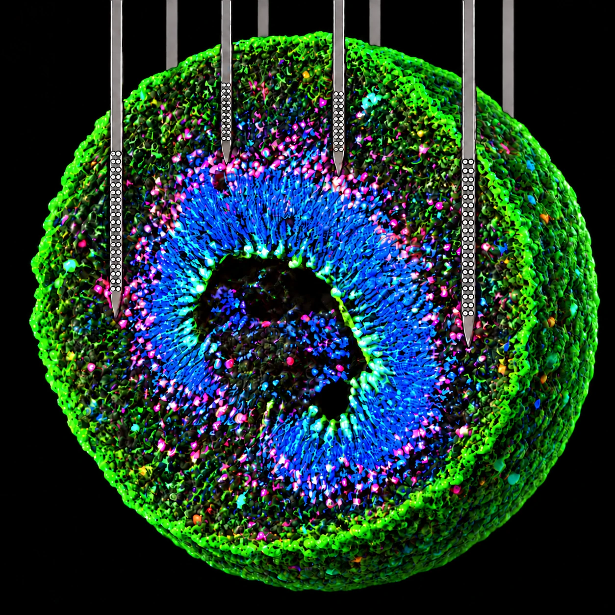
Figure 1. Conceptual cutaway illustration: penetrating shanks place sites through the organoid's layers rather than on its surface.
What question does recording inside the organoid answer?#
A brain organoid is a three-dimensional tissue, and its neurons are distributed through the volume. Published work on human cortical organoids has shown spontaneous spiking, network oscillations that develop over months, and pharmacological responses, which makes electrical recording a direct functional readout alongside imaging and molecular assays (Trujillo et al., 2019; Sharf et al., 2022). A planar multi-electrode array records at the one surface the organoid rests on. IntraSense+ places sites inside the tissue, at depths and lateral positions chosen for the layers under study, so the recording geometry can be matched to the organoid's architecture rather than to its footprint.
Two kinds of signal come out of the same recording. Fast transients give access to spikes from nearby neurons; the lower-frequency local field potential reports population activity and network rhythms. Together they connect activity at individual sites with the timing and organization of larger populations.
What does the system consist of?#
IntraSense+ is a complete solution for organoid electrophysiology, and each part is usable on its own: the organoid platform (a sample chamber with organoid baskets, probe positioning, and a camera on the interface), penetrating silicon probes in single-plane and three-dimensional geometries, a NeuroNexus data acquisition system, and Radiens software. A laboratory can adopt the whole system, add the probes and positioning to acquisition hardware and software it already runs, or start from the probe geometry its question needs. Compatible third-party acquisition systems and software connect to NeuroNexus probes through the usual headstage and adapter path.
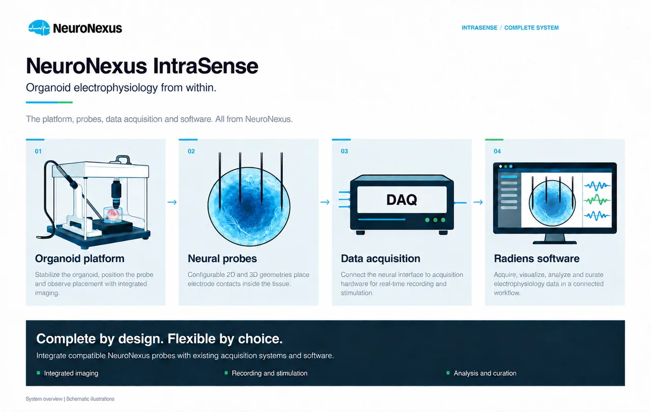
Figure 2. The four parts of the system, shown schematically.
How are sites placed inside the organoid?#
Both geometries put sites inside the tissue; they differ in how the sites are arranged. A 2D probe positions sites at selected depths and lateral locations within one plane, with shank length and site layout chosen to meet the intended neuronal layers. A 3D array distributes sites across more than one plane, for comparisons between internal regions and depths within one organoid.
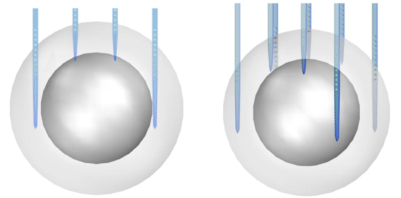
Figure 3. Conceptual renderings of a 2D probe (left) and a 3D array (right) inside an organoid. The renderings show geometry, not a fixed configuration.
The configuration is chosen against the organoid and the question. The system is configured for organoids 2 to 5 mm in diameter. Channel counts are 16 or 32 with the integrated drive mount, and 64, 128 or 256 with an external drive. Probes have 1 to 8 shanks, 3 to 10 mm long, on 15 or 50 µm silicon, with linear, Buzsaki, polytrode, tetrode, edge or custom site layouts, and SIROF or Z-Coat™ sites. Shank length gives the reach; site placement defines the sampled region; multiple entry points and depths raise the number of locations one organoid yields.
| Parameter | Options |
|---|---|
| Organoid diameter | 2–5 mm |
| Channels | 16 or 32 with the integrated drive mount; 64, 128 or 256 with an external drive |
| Geometry | 2D single-plane; 3D penetrating array |
| Site layout | Linear, Buzsaki, polytrode, tetrode, edge, custom |
| Substrate thickness | 15 or 50 µm |
| Shanks | 1–8; 3–10 mm |
| Site material | SIROF or Z-Coat |
Probe-tip shape and shank geometry are designed for tissue entry with little dimpling at the organoid surface, so the site-bearing segment ends up in the intended tissue region. Sputtered iridium oxide (SIROF) and Z-Coat sites have low impedance and high charge-storage capacity: low impedance for a low noise floor on recording, charge capacity for stimulation. The same probe can therefore be configured to record and stimulate, with the charge-injection limits and operating parameters set for the chosen stimulation protocol.
How does a recording session run?#
The recording assembly brings probe positioning, sample support and close-up viewing together in a unit built for use inside a conventional cell-culture incubator. The organoid sits in a basket in the sample chamber; it is not compressed and not attached to a planar substrate with an adhesion coating, and it is retrieved intact after the probe is withdrawn. The camera gives a close view of the shanks as they enter the tissue while the traces are watched live, so insertion depth is adjusted on both the picture and the signal; changes in activity across sites as the probe advances are the functional guide to the target layer. Medium, gas conditions and tissue-health measurements remain part of the laboratory's own culture protocol. Cable management and a stable base let the assembly be moved between experiments, and the supplied cleaning system supports electrode reuse within the laboratory's cleaning and inspection routine.
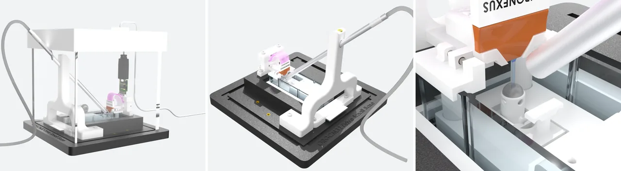
Figure 4. System renderings: enclosed system, open assembly, and probe placement with the integrated camera near the organoid.
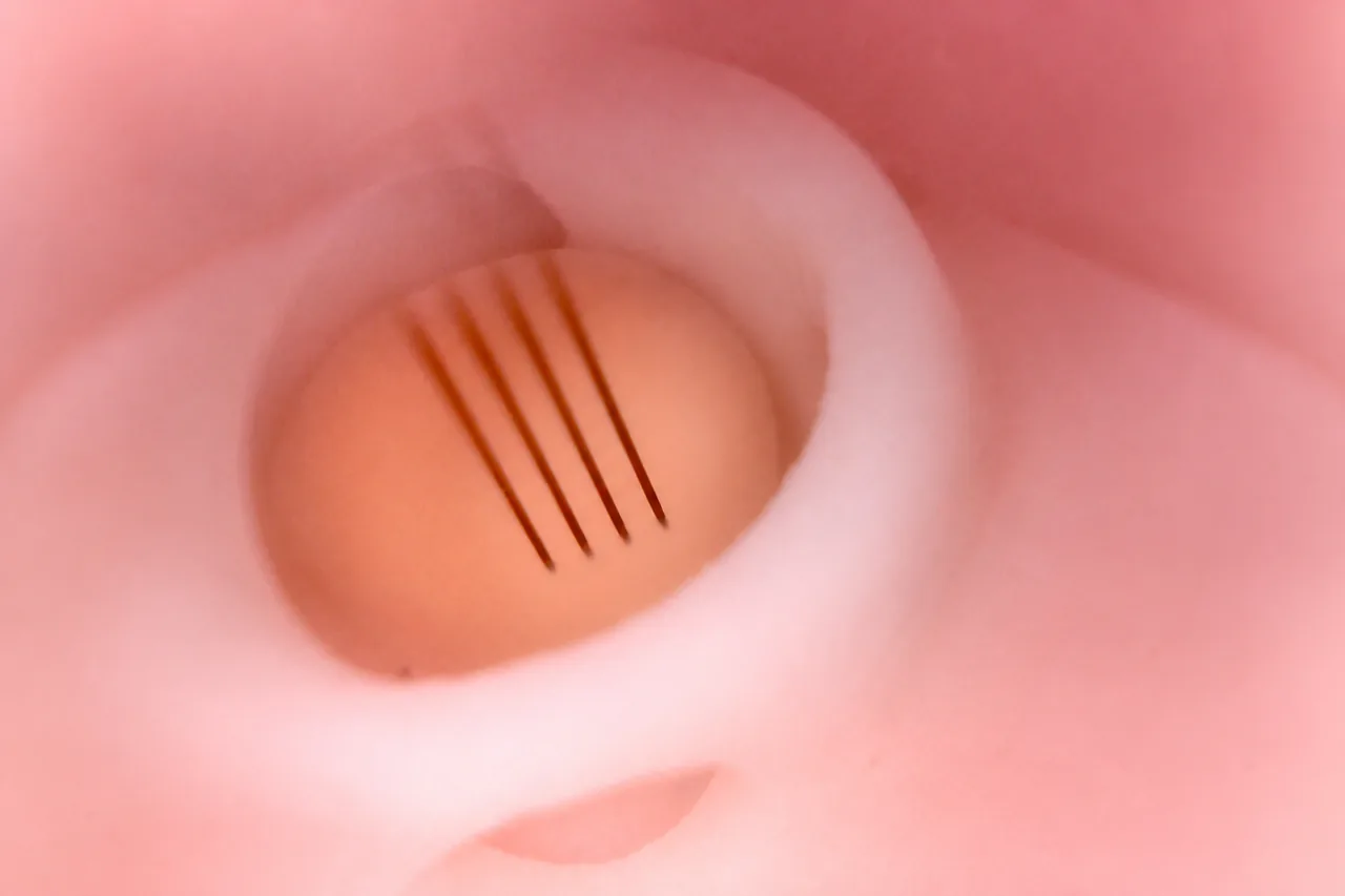
Figure 5. The assembly inside a conventional incubator.
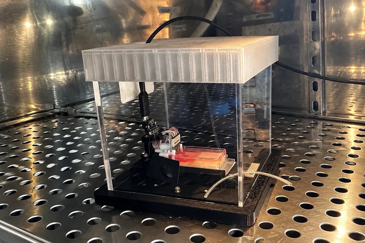
Figure 6. The integrated camera's view during probe insertion.
What do the recordings look like?#
Radiens connects acquisition, spatial display, analysis and curation. Allego ↗ acquires and shows the live signal; its 3D view places activity on the probe geometry, with amplitude-coded markers at each site and the organoid model in the same space; Videre ↗ runs spike sorting, field-potential and spectral analysis and curation afterward; local storage, NWB ↗ export and RadiensPy ↗ connect the data to the laboratory's own analysis.
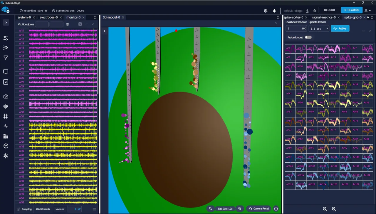
Figure 7. Allego during organoid acquisition: traces (left), the 3D organoid and probe model (center), sorted spike waveforms (right). Marker size follows activity amplitude near each site.
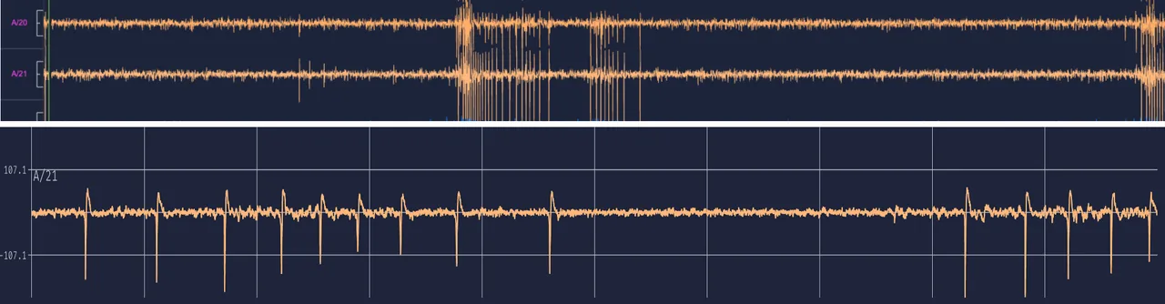
Figure 8. Channels A/20 and A/21 in an overview recording, then an expanded time view of A/21.
The overview connects events across sites and shows periods of elevated activity; the expanded view resolves individual transients for inspection of shape and timing. Spike detection and sorting take these to event trains and, where quality criteria are met, isolated units; field and spectral analyses take the same recording to slower population activity.
The NeuroNexus technical dataset behind this note holds about 130 recording sessions and 633 recordings, about 1 TB of data. In one dataset, activity was detected at 834 of 1,056 sites, about 79%; the figure is site-based and is read with the organoid model, site placement and recording conditions of that dataset, not as a specification.
How is signal quality reported?#
Allego and Vantage show per-channel signal quality during the recording: signal-to-noise ratio against the estimated background, noise floor, and activity, so productive sites are identified and coupling assessed during the session rather than after it. Reports carry per-channel rankings, noise distributions and time-resolved views. As an illustration of the reporting, a 600-second, 32-channel recording at 30 kHz is summarized as median SNR 5.0, noise floor 4 µV, event rate 1.2 Hz and 28 of 32 good channels; the values illustrate the report, not a product specification. Curation keeps the quality with the data: channel and window selections are non-destructive, processing history is retained, and dataset identifiers and provenance tie results to raw measurements. For comparisons within a study, one set of signal, noise and event definitions is used throughout.
Can the same organoid be recorded across days?#
Yes. Penetrating access and incubator-compatible operation support longitudinal work: the organoid is recorded, returned to culture, and recorded again. Figure 9 shows rasters from one preparation on two days; rows are channels, marks are detected events, and the shaded intervals are network bursts. Event timing, firing patterns and network features can then be compared across sessions of maturation, perturbation and recovery while they stay tied to the same sites and specimen. Nutrient supply, medium exchange and tissue-health assessment supply the biological context for any change in activity.
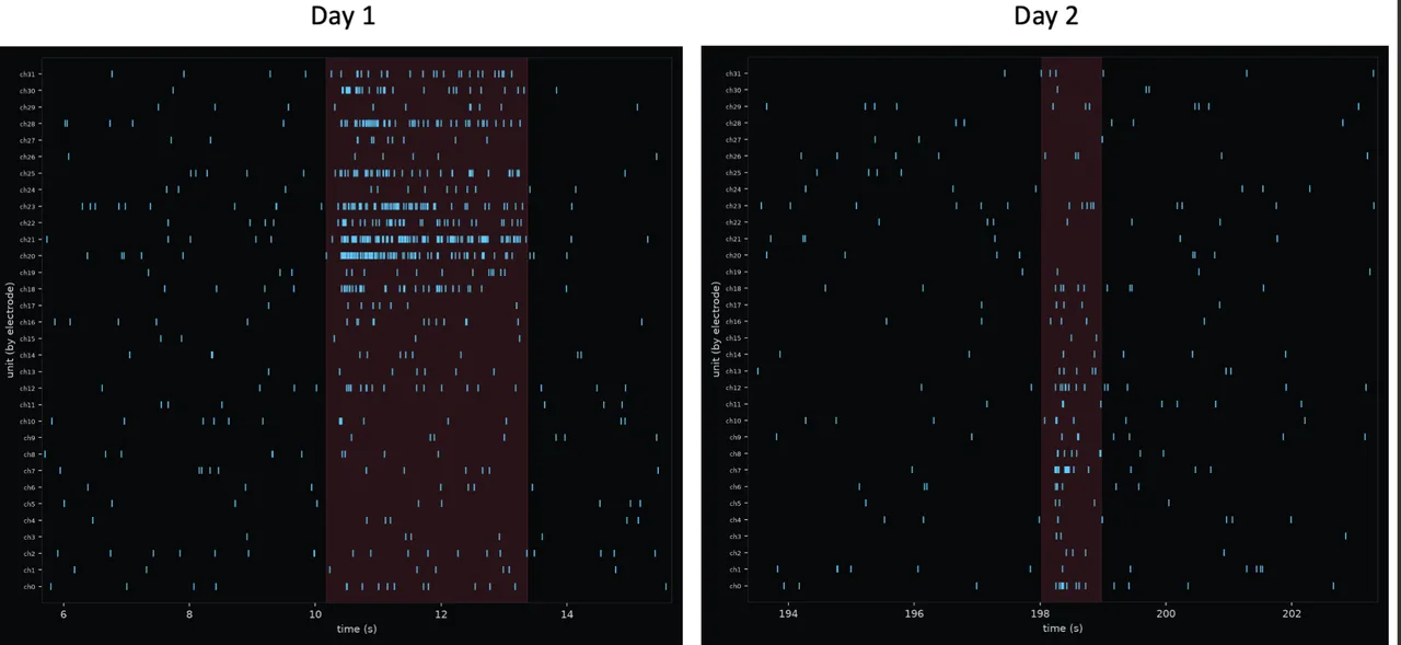
Figure 9. Rasters from the same preparation on two days. Each row is a channel; shaded intervals mark network bursts.
How does it compare with a planar MEA?#
NeuroNexus compared penetrating recordings with a commercial planar CMOS MEA on seven-month-old cortical organoids from the same culture plate on the same day. Both interfaces detected spiking, with comparable spike detection in this example; the comparison is qualitative, and the two displays use their own scales and layouts. What the penetrating geometry adds is the location of the sites: inside the organoid, at chosen depths, with more than one entry point, which is what a question about a particular cellular layer or a comparison across depths requires. Surface mapping and internal recording are different spatial views of the same tissue, and the interface is chosen by the question.
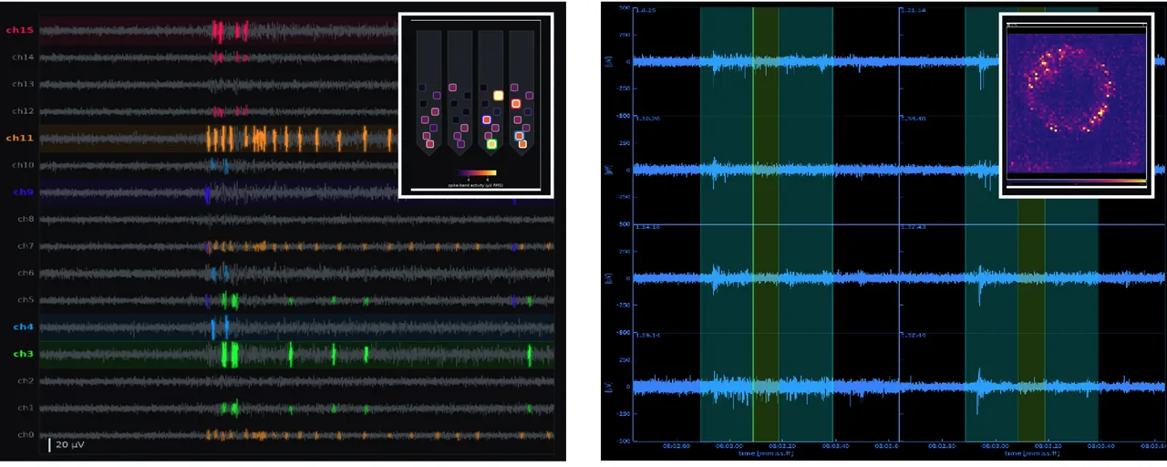
Figure 10. Penetrating recording (left) and a commercial planar CMOS MEA (right), each with its activity-map inset. Qualitative comparison.
How is a study designed around it?#
Start with the biological target: the organoid model, the tissue regions and the functional endpoints. Shank length, site placement and array configuration follow from the locations and spatial relationships the experiment has to resolve. The catalog's 210+ silicon probe designs cover most combinations of shank length, site layout and channel count; where none fits, NeuroNexus designs a custom probe around the tissue access, shank geometry, site placement and interface the question needs. Application Scientists match probe selection to the organoid model and objective.
| Objective | What answers it |
|---|---|
| Access internal tissue | Penetrating shanks with sites at selected positions and depths |
| Compare spatial regions | Configurable layouts; single-plane or 3D arrays |
| Observe the interface | Integrated camera during insertion |
| Record in culture conditions | Incubator-compatible assembly and sample handling |
| Interpret activity | Radiens acquisition, spatial views, signal-quality review, analysis |
| Extend the analysis | Local storage, NWB export, RadiensPy |
How is it ordered?#
IntraSense+ is available by quote, configured for the organoid and the question: the organoid platform, the probes, the acquisition system and Radiens together, or the parts a laboratory needs beside equipment it already has. The configuration options above are the starting point; a quote fixes the probe designs, channel count and drive. The technical application note this document ports is available as a PDF: IntraSense+ technical application note ↗ (14 pages). To configure a system, start at Organoid Electrophysiology.