Photoelectric Artifact in Silicon Probes
What the photoelectric artifact is, what sets its size, and how NeuroNexus removes it at the electrode: Z-Coat at the site, optrode packages at the light path.
7 min read
Updated November 4, 2026

NeuroNexus · neuronexus.com · Resources
The photoelectric artifact is the voltage transient a light pulse produces on a metal recording site, time-locked to the pulse and inside the window where the optogenetic response falls. Its size is set by the irradiance at the site, the exposed metal area, the site interface, and the pulse edges. NeuroNexus removes it at the electrode: Z-Coat changes the site interface so the transient is suppressed, and optrode packages place the fiber so the sites are not lit directly.
Research use only. NeuroNexus products and the procedures described here are for non-clinical research use, and must not be used in human or veterinary medical procedures.
What is the photoelectric artifact?#
When a light pulse strikes the metal of a recording site, the site's potential moves. Photons release charge at the metal surface, the illuminated metal–electrolyte interface shifts its equilibrium potential (the Becquerel effect), and the absorbed energy heats the interface and the fluid beside it. The amplifier records the sum as a transient on the channel (Kozai & Vazquez (2015) ↗). It is an electrode response to light, not neural activity, and it is time-locked to the pulse: a fast deflection at onset, a slower drift during a long pulse, and a second deflection at offset. In an optogenetic experiment those are the same milliseconds in which the evoked spikes and field potentials arrive, which is why the artifact is a problem of the experiment and not of the display (Cardin et al. (2010) ↗).
What sets its size?#
Four things, in the order a probe designer controls them.
Irradiance at the site. The transient scales with the light that reaches the metal. Irradiance falls steeply with distance from the fiber tip and with scattering in tissue, so a site a few hundred micrometers from the tip, off the fiber's axis, receives a small fraction of what a site in front of it receives. Fiber placement relative to the sites is the first lever.
Exposed metal area. A larger bare metal area collects more photons and produces a larger transient. Site area is fixed by the design, so the lever is what covers the metal, not how much of it there is.
The site interface. The transient is generated at the metal–electrolyte boundary, and what that boundary is made of sets how much charge light releases there and how the amplifier sees it. A low-impedance interface that is not bare metal responds differently from a bare iridium or platinum surface (Cogan (2008) ↗).
The pulse edges. The deflections are largest where illumination changes fastest, at onset and offset; a long pulse adds the slower thermal component between them. Pulse shape is the experimenter's lever, and it is the one that costs temporal resolution.
How does NeuroNexus remove it?#
NeuroNexus removes the artifact at the electrode, before it reaches the amplifier, rather than subtracting it afterwards, at two levels.
Z-Coat, at the site interface. Z-Coat is the proprietary NeuroNexus site coating. It lowers site impedance by roughly an order of magnitude at the same footprint, which lowers the noise floor and raises the charge a site can deliver, and it changes the interface light strikes, so the photoelectric transient is suppressed at the site. The coating is mechanically stable through repeated insertion, so the suppression holds across the sessions of a chronic implant rather than fading with a delaminating polymer. Z-Coat is specified at order as a site option on catalog silicon probe designs; the coating, its stability, and its use for stimulation are in Z-Coat: Optimized Site Coating for Stimulation and Noise Reduction.
Optrode packages and the oDrive, at the light path. An optoelectrode package fixes the fiber alongside the array at assembly, on the same trajectory as the recording sites, so the light is delivered where the recording is made and the sites are not lit head-on. Builds exist on the A-Series, CM, Hybrid, ZIF, Q-Trode, Vector, drug-delivery, and Activus SiNAPS package series (OA32LP, OCM16LP, OH32LP, OZ32LP, OCQ4LP, OV32, OD16LP, OAVS256 and their siblings), with the fiber's core, cladding, numerical aperture, and length confirmed on the quotation. The light pulse is timestamped with the neural data through GPIO, so onset and offset are known to the sample, and XDAQ ALL-IN-ONE drives up to four optogenetic channels itself. For a chronic preparation the oDrive microdrive holds an optrode package and advances it over the weeks of the study.
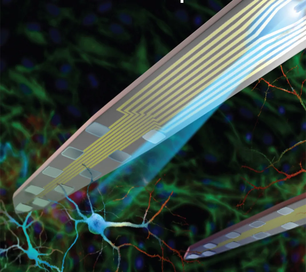
Figure 1. An optoelectrode: the optical fiber fixed alongside the silicon array, so light is delivered on the trajectory of the recording sites.
What does a clean optogenetic recording look like?#
The trace through the pulse is the test. On a Z-Coat site in an optrode build the channel shows no ramp at pulse onset and no rebound at offset: the baseline runs through the pulse, the units that were firing before the pulse are visible during it, and the light-evoked spikes are separable from the pulse edge by their waveform and latency rather than by a blanking window. The non-expressing control, the same pulse in an animal without the opsin, is flat. A measured series, artifact amplitude and settling time by site coating and by fiber-to-site distance under stated illumination, is added to this document as a table when the application-science measurements are complete.
Which configuration?#
Specify Z-Coat on any design that will record through light pulses; it is a per-channel site option on the design you have already chosen, and it also lowers the noise floor and raises safe charge delivery, so it is rarely the wrong choice. Specify an optrode package when the light and the recording belong on the same trajectory: optogenetic tagging, closed-loop stimulation, and circuit dissection on one shank. When the manipulation is wide-field and read from a distant structure, a separate fiber keeps the cross-section of the array small and the light off the sites altogether. The Electrode Finder narrows the catalog by site count, pitch, depth, and shank layout, and every design's datasheet lists the package series, including the optoelectrode builds, it is offered in. Optoelectrodes: Silicon Probes for Optogenetics sets out the three decisions of an optogenetics setup.
Representative examples#
Representative examples of recording through optical stimulation on multi-shank silicon probes with fibers include Royer et al. (2010) ↗, who recorded local circuits in behaving animals through fibers integrated on the probe, and Stark et al. (2012) ↗, who placed diodes on silicon arrays for spatiotemporal control of multiple neurons in freely moving animals; the artifact itself and the recording protocol that keeps it separable are in Cardin et al. (2010) ↗, and its physics in Kozai & Vazquez (2015) ↗. Further examples are in the NeuroNexus citation database.
Do NeuroNexus silicon probes produce a photoelectric artifact under optogenetic stimulation?#
NeuroNexus addresses the artifact at the electrode. Z-Coat site coating suppresses the photoelectric artifact that light produces on a metal recording site and holds through repeated insertion; optrode packages place the fiber so the sites are not lit directly, and the light pulse is timestamped with the neural data through GPIO.
Related documents#
- Z-Coat: Optimized Site Coating for Stimulation and Noise Reduction
- Optoelectrodes: Silicon Probes for Optogenetics
- NeuroNexus Probe Technology: Questions and Answers
- Photoelectric artifact, in the glossary
Citations#
- Kozai, T. D. Y., and Vazquez, A. L. (2015). Photoelectric artefact from optogenetics and imaging on microelectrodes and bioelectronics: new challenges and opportunities. Journal of Materials Chemistry B 3, 4965–4978. 10.1039/C5TB00108K ↗
- Cardin, J. A., Carlén, M., Meletis, K., Knoblich, U., Zhang, F., Deisseroth, K., Tsai, L.-H., and Moore, C. I. (2010). Targeted optogenetic stimulation and recording of neurons in vivo using cell-type-specific expression of Channelrhodopsin-2. Nature Protocols 5, 247–254. 10.1038/nprot.2009.228 ↗
- Royer, S., Zemelman, B. V., Barbic, M., Losonczy, A., Buzsáki, G., and Magee, J. C. (2010). Multi-array silicon probes with integrated optical fibers: light-assisted perturbation and recording of local neural circuits in the behaving animal. European Journal of Neuroscience 31, 2279–2291. 10.1111/j.1460-9568.2010.07250.x ↗
- Stark, E., Koos, T., and Buzsáki, G. (2012). Diode probes for spatiotemporal optical control of multiple neurons in freely moving animals. Journal of Neurophysiology 108, 349–363. 10.1152/jn.00153.2012 ↗
- Cogan, S. F. (2008). Neural stimulation and recording electrodes. Annual Review of Biomedical Engineering 10, 275–309. 10.1146/annurev.bioeng.10.061807.160518 ↗