Choosing a Probe Package
What a probe package is, why it matters as much as the array, and how acute or chronic, the subject, and the headstage select one of fourteen series.
14 min read
Updated October 27, 2026

NeuroNexus · neuronexus.com · Resources
A probe package is the connector assembly built onto an electrode array, the interconnect, connector, and covering that connect every site to a pin a headstage mates to, and it decides how the probe is held, what it plugs into, how much it weighs on the animal, and how long it survives. NeuroNexus offers fourteen package series for the same array. Three questions select one: acute or chronic, what the subject can bear, and which headstage will read it.
Research use only. NeuroNexus products are for non-clinical research use and must not be used in human or veterinary medical procedures.

Figure 1. Assembled probes: the same kind of electrode array in different packages, each with its own connector, cable, and body.
What is a probe package?#
A finished NeuroNexus probe has two parts. The electrode array is the microfabricated part: the shank or shanks with their electrode sites, and a base with the bond pads where each site's trace terminates. The package is everything assembled around that base to make the array usable: an interconnect that runs from the bond pads to a connector (a rigid printed-circuit board, a flexible polyimide cable, or none at all when the connector sits on the assembly itself), the connector a headstage mates to (Omnetics, Samtec, Hirose, Molex X3, a zero-insertion-force connector, or a four-pin CQ4 for a single tetrode), a protective covering over the bond region, a housing where the preparation needs one, and the ground and reference wires brought out beside the signal pins. NeuroNexus assembles the package by hand: the array's pads are bonded to the interconnect, the bond region is encapsulated, and strain relief is added where a cable meets a connector.
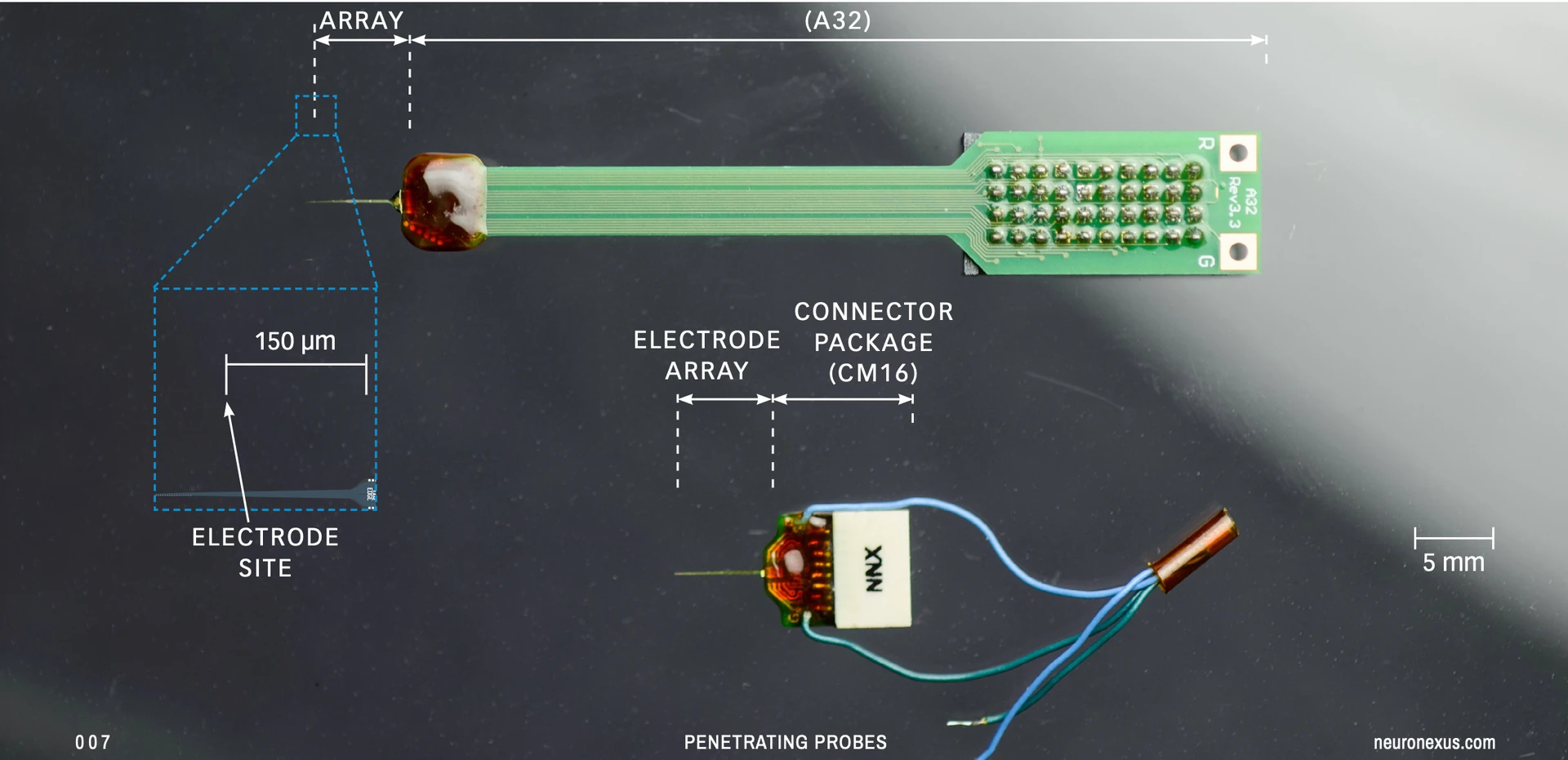
Figure 2. The two parts of a probe. (Top) A single-shank array on an A32 package: a rigid printed-circuit interconnect ending in a connector, for acute work. (Bottom) The same kind of array on a CM16 package: the connector mounted on the assembly with no cable, for a chronic mouse implant, with breakout ground and reference wires.
The two parts are decoupled by design. The array is chosen for the target, from the 216 catalog silicon designs, and the package is chosen for the preparation and the rig; the same array can be ordered on several packages, and an A-Series package accepts 128 catalog designs, a Hybrid package 141. A package name reads as the series and the channel count: A32 is an A-Series package with 32 channels, CM32 a CM package with 32, H64 a Hybrid with 64; a leading O marks an optoelectrode build with an optical fiber (OH32LP), MR an MRI-conditional build with non-magnetic parts (MRA16, MRCM16LP), and VC a chronic Vector build (VC64). A probe is ordered as the array design plus the package, and the package is built onto the array at assembly, so it is decided once; a probe in a different package is a different product.
Why does the package matter as much as the array?#
The recording sites are the same on an acute and a chronic probe. What differs is the rest of it, and the rest decides whether the recording reaches the amplifier and for how long. The package decides how the probe is held, in a stereotaxic manipulator or cemented to the skull; what it mates to, because the connector fixes which headstage can read it; how much it weighs on the animal, from 0.14 g for a Hybrid to several grams for an A-Series board; where the reference and ground come out; what else shares the trajectory, an optical fiber, a fluidic channel, a second array; and how long it survives, because the bonds, the encapsulation, and the body carry the mechanical load the array never sees. A large share of field failures in thin-film electrodes originate in the package, and most of those were decided at order. NeuroNexus holds the package to the same standard as the array, as What Makes a Thin-Film Electrode Good sets out, and the published chronic record of silicon probes rests on packages that held for months (Kipke et al. (2003) ↗; Vetter et al. (2004) ↗; Okun et al. (2016) ↗). This guide is the package decision in the order it binds; the array it is built around is chosen first, in Choosing an Electrode for Your Experiment.
Is the preparation acute or chronic?#
This is the first question because it changes what the package is for. An acute package is built to be held: it mounts on a micromanipulator, goes into the animal for one session, comes out, is cleaned, and is used again. Its priorities are handling and reuse, its failure mode is site damage from handling, and it tolerates a large connector because nothing has to carry it. A chronic package is built to be worn: it is cemented to the skull, stays for weeks to months, and takes the load of a tether and of an animal that grooms, climbs, and sleeps against the cage without passing that load to the shank. Its priorities are fixation, strain relief, and connector durability; its failure mode is mechanical; and it is used once.
The choice follows from the measurement. Chronic when the same neurons are needed on more than one day, for learning, plasticity, disease progression, or sleep, or when the animal must move freely; acute otherwise, because it is faster, less costly, re-targets each session while a study is still being mapped, and shows what to build the chronic study around. An acute session that fails costs a day; a chronic implant that fails at week six costs the animal, the surgery, and the six weeks, which is why researchers typically choose acute where both would serve.
Two consequences follow. Reference and ground differ: an acute preparation can use a reference wire in a saline-filled craniotomy and adjust it during the session, while a chronic implant fixes a bone-screw reference at surgery because nothing is adjustable afterward. And channel count is a separate axis: more channels do not rescue an implant that moves, and they add weight, cable stiffness, and headcap volume, each of which makes a chronic implant harder to keep alive.
Which acute package?#
The A-Series is the default acute package: the probe on a rigid printed-circuit interconnect that ends in a standard connector, held in a stereotaxic manipulator. It takes 128 catalog silicon designs of 1 to 8 shanks and 2 to 15 mm, and the site count sets the connector: DIP pins at 16 sites, Samtec 40-pin from 32 to 96, Omnetics 32-pin at 128. A32 is the 32-channel build most laboratories start with. Its MRI-conditional variant, MRA16, replaces the connector and hardware with non-magnetic parts for recording inside a scanner.
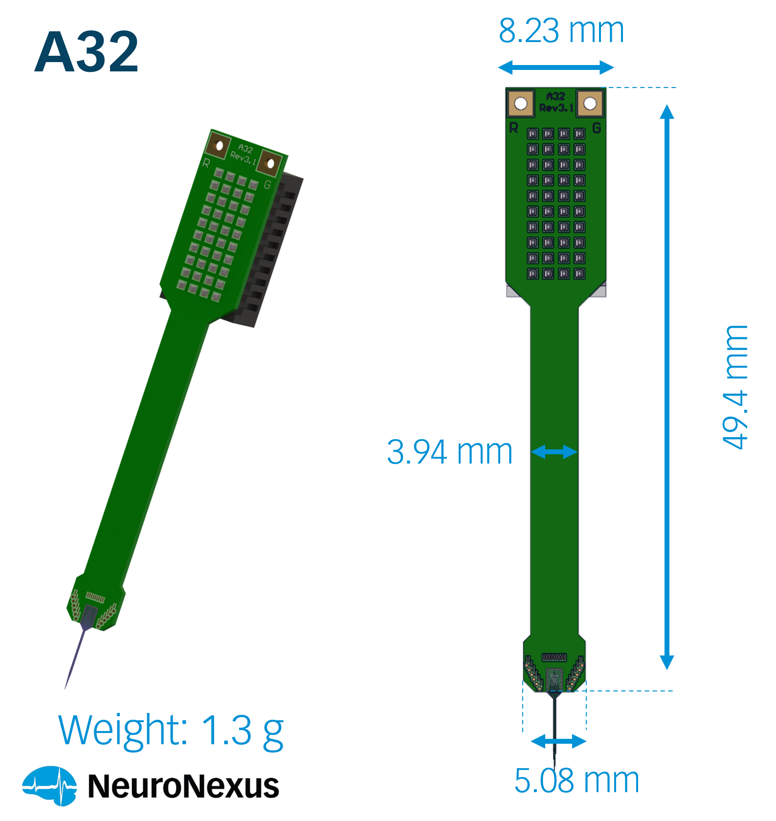
Figure 3. A32, the default acute package: a rigid printed-circuit interconnect for a stereotaxic holder, reused across sessions.
Two acute alternatives answer specific constraints. The ZIF series (Z32) terminates in a zero-insertion-force connector for TDT ZIF-Clip headstages, so the cable seats with almost no force and spares a delicate shank at every headstage change; the trade is a connector with a moving part. The EIB series is a passive interface board that brings 64 channels out on two Molex 34-pin board-to-board connectors with no active electronics in the assembly, for laboratories that route their own.
Which chronic package?#
Three chronic series answer three constraints, and the subject decides between them.
Weight. The CM series (CM32) mounts the Omnetics connector directly on the assembly with no interconnect cable, which keeps the footprint small and the weight low; it is the usual chronic package for a mouse, and it has MRI-conditional variants (MRCM16LP). The X-Series package (X3-32) is the smallest-footprint, lowest-mass assembly in the range, on a Molex X3 connector that an X-Series headstage mates to directly with no adapter in the stack; chronic builds add a 10 to 30 mm flexible cable. NeuroNexus recommends it where head weight and profile are the binding constraints and the recording chain is X-Series.
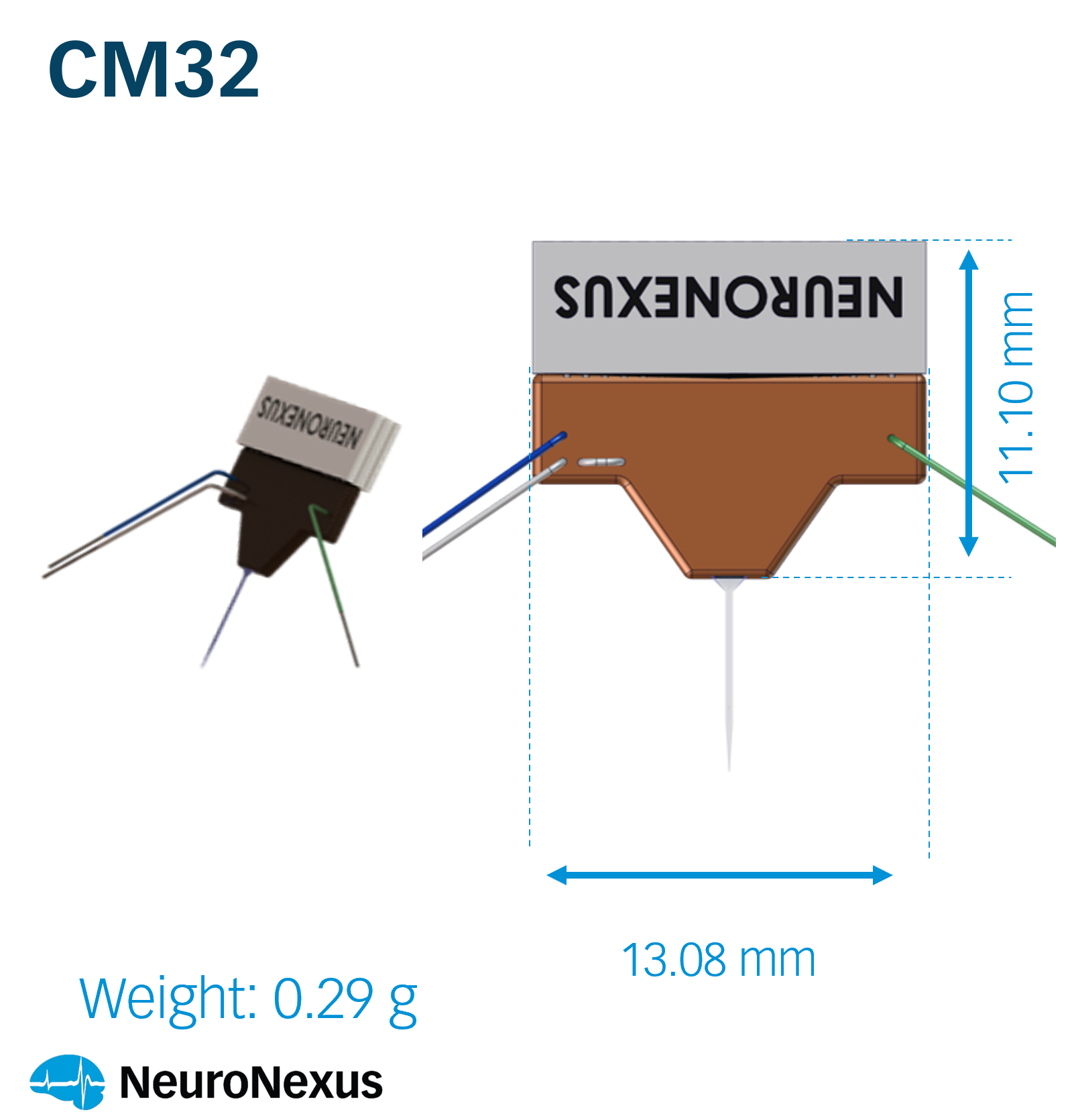
Figure 4. CM32, the usual chronic package for a mouse: the connector on the assembly, no cable, the smallest footprint on an Omnetics connector.
Decoupling. The Hybrid series (H32; H for hybrid assembly, a thin-film silicon probe on one end of a thin-film polymer ribbon cable with the PCB and connector on the other) puts a flexible thin-film polyimide cable between the array and the connector, so the probe is mechanically uncoupled from the head-fixed connector and moves with the tissue rather than being held rigid against it. It is the choice for a floating implant, for connector stand-off, and for use with a microdrive that adjusts depth after implantation; with 141 compatible designs from 1 to 16 shanks and 2 to 60 mm it has the widest compatibility of any series, and it has MRI-conditional builds.
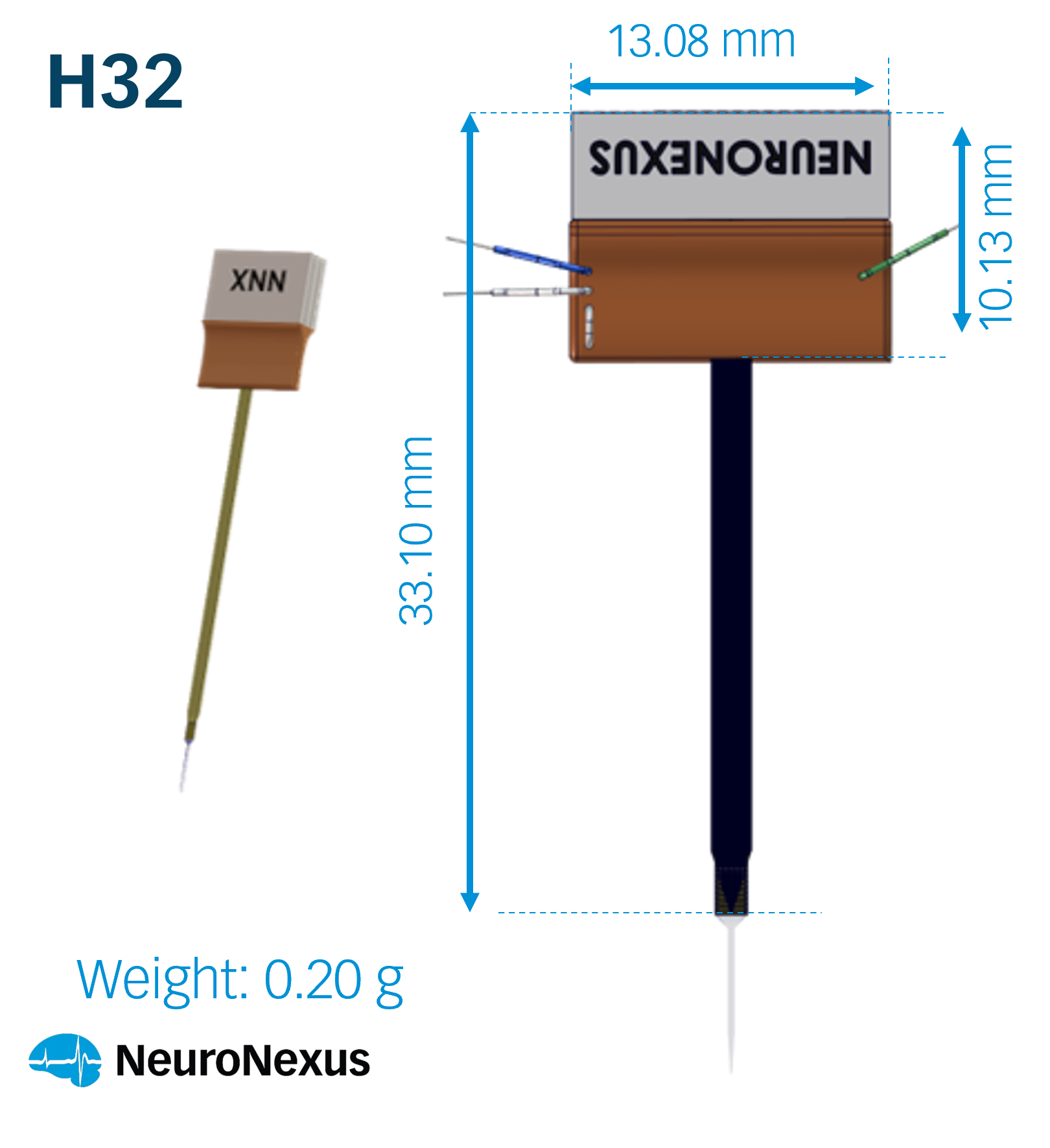
Figure 5. H32, the Hybrid package: a flexible polyimide cable between the array and the connector, for a floating chronic implant or a microdrive.
Trajectory. For a deep target in a large animal, the Vector chronic builds (VC64) configure the array's 70 or 110 mm support body to an implantable 30 to 55 mm for a chamber and microdrive, on Omnetics or ZIF-Clip.
A 30 g mouse is not a small rat. The same headcap a rat tolerates for months changes a mouse's gait, so the implant's weight, connector, cable, and headstage together, is budgeted at selection, alongside the geometry, rather than after the package is chosen. Measured package weights are on each package datasheet.
Which headstage will read it?#
The connector fixes what the probe can talk to, and the package is where the connector is chosen. Omnetics, on the A-Series, CM, Hybrid, Vector, and DBS series, mates NeuroNexus and most third-party headstages through the standard pinout. Hirose, on the ZIF, Hybrid HZ, and Vector VZ builds, serves laboratories on TDT ZIF-Clip systems. The Molex X3 connector on X-Series packages mates an X-Series headstage directly. And the Activus series (AV64) integrates a digitizing headstage chip into the package itself, on micro-HDMI or Omnetics, so the analog path ends millimeters from the sites, for 16 to 256 channels on acute or chronic preparations, mice to primates.
Site count sets the channel count and the channel count sets the connector: 16 and 32 channels on one connector, 64 on one or two, 128 and above on several 32-pin connectors or a high-density package. For the Matrix 3D platform (MH128), 64 to 256 channels terminate in a percutaneous connector; for SiNAPS active-pixel probes, 256 and 1,024+ channels come out on a 50-pin Samtec connector with no headstage at all. Where a package and a headstage are not native to each other, an adapter joins them; the pairings, and the cases that leave sites or channels unused, are tabulated in Connecting a Probe Package to a Headstage: Which Adapter?.
What else must share the trajectory?#
Some experiments need more than sites on the shank, and those are package builds rather than separate products. Optoelectrode builds add an optical fiber alongside the array so light is delivered where the recording is made: OH32LP on the Hybrid series, and equivalents on the A-Series, CM, ZIF, Q-Trode, Vector, drug-delivery, and Activus SiNAPS series; every optoelectrode adds cross-section along the whole trajectory and a photoelectric artifact at light onset that the analysis window allows for. The drug-delivery series (D16) adds a stainless-steel fluidic channel beside a 16-site array so a compound is infused and its effect recorded at one place. The Fusion series bonds two arrays back to back on one shank, doubling the site count in the same cross-section, and brings the doubled count out on several 16- or 32-pin connectors. The Q-Trode series mounts one tetrode on a four-channel CQ4 connector, light enough that head weight is never the limit. The DBS series routes an rDBSA lead's 32 contacts to a threaded Omnetics connector for stimulation and recording at depth. MRI-conditional builds exist inside the A-Series, CM, Hybrid, and optoelectrode series rather than as a series of their own.
The fourteen series at a glance#
| Series | What it is | Connector | Preparation | Example |
|---|---|---|---|---|
| A-Series | rigid printed-circuit interconnect for a stereotaxic holder | DIP, Samtec, Omnetics | acute, intra-operative | A32 |
| ZIF | zero-insertion-force connector | Hirose (TDT ZIF-Clip) | acute | Z32 |
| EIB | passive interface board, 64 channels | 2 × Molex 34-pin | acute | EIB64 |
| CM | connector on the assembly, no cable | Omnetics | chronic, mouse | CM32 |
| X-Series | smallest footprint and mass; mates an X-Series headstage directly | Molex X3, Panasonic | chronic, freely moving | X3-32 |
| Hybrid | flexible polyimide cable between array and connector | Omnetics, Hirose (HZ) | chronic, floating, microdrive | H32 |
| Vector | short array on a rigid support body for deep targets | Omnetics, ZIF-Clip | acute or chronic, large animal | V64, VC64 |
| Matrix | 3D platform of 2D arrays on a flexible cable | percutaneous connector | chronic | MH128 |
| Activus | digitizing headstage chip integrated in the package | micro-HDMI, Omnetics 12 | acute or chronic | AV64 |
| Activus SiNAPS | active-pixel probe package, no headstage | 50-pin Samtec | acute or chronic | AVS1024 |
| Q-Trode | one tetrode on a four-channel connector | CQ4 | chronic, light | Q4 |
| Fusion | two arrays bonded back to back on one shank | several 16- or 32-pin | acute or chronic | — |
| Drug delivery | fluidic channel beside a 16-site array | Omnetics | acute or chronic | D16 |
| DBS | rDBSA lead, 32 contacts | threaded Omnetics | large animal | — |
Putting it together#
Decide acute or chronic from the measurement. If acute, A32 unless a ZIF-Clip system or an MRI scanner says otherwise. If chronic, CM32 for a mouse, X3-32 where an X-Series headstage will read it and mass is the limit, H32 for a floating implant or a microdrive, VC64 for a deep target in a large animal. Add the optoelectrode, fluidic, Fusion, or MR build if the experiment needs it, and confirm the connector against the headstage before ordering; NeuroNexus Application Scientists confirm the pairing with the quote. The surgical steps that follow are in the acute and chronic surgical guides, and every package series has its own glossary entry and datasheet. Browse electrode packages.
Related documents#
- Read next, in order: Choosing an Electrode for Your Experiment · Connecting a Probe Package to a Headstage: Which Adapter? · What Makes a Thin-Film Electrode Good · Silicon Probes and Thin-Film Grids: An Introduction · The Electrode Design Space
- Surgery and care: Surgical Guide: Acute Silicon Probes for Neural Recording · Surgical Guide: Silicon Probes, Chronic Implantation · Silicon Probes: Setup, Handling, Cleaning and Care
- Glossary: Probe package · Headstage · Adapter · Recording chain · MRI-conditional package · Optoelectrode package · Acute recording · Chronic recording
Citations#
- Kipke, D. R., Vetter, R. J., Williams, J. C., & Hetke, J. F. (2003). Silicon-substrate intracortical microelectrode arrays for long-term recording of neuronal spike activity in cerebral cortex. IEEE Transactions on Neural Systems and Rehabilitation Engineering, 11(2), 151–155. DOI: 10.1109/TNSRE.2003.814443 ↗
- Vetter, R. J., et al. (2004). Chronic neural recording using silicon-substrate microelectrode arrays implanted in cerebral cortex. IEEE Transactions on Biomedical Engineering, 51(6), 896–904. DOI: 10.1109/TBME.2004.826680 ↗
- Okun, M., et al. (2016). Long term recordings with immobile silicon probes in the mouse cortex. PLOS ONE, 11(3), e0151180. DOI: 10.1371/journal.pone.0151180 ↗